10+ dependency diagram
In the bike parts diagram above Ive labelled some of the most important bicycle components. UML Class Diagrams is a type of static structure diagram that is used for general conceptual modeling of the systematics of the application.
Graphing Xcode Project Dependencies Introducing Xcgrapher By Max Chuquimia Itnext
UML Use Case Diagram.

. Component diagrams are used to visualize the organization of system components and the dependency relationships. In a project network a dependency is a link among a projects terminal elements. A smarter way of using PowerPoint Fishbone diagram template.
A diagram is a symbolic representation of information using visualization techniques. In this component diagram tutorial we will look at what a component diagram is component diagram symbols and how to draw one. Such a diagram would illustrate the object-oriented view of a system.
When it comes to system construction a class diagram is the most widely used diagram. There are two main reasons for using PowerPoint to draw the diagram. This factory assigns an HttpMessageHandler from a pool to the.
The arrow head represents the independent element and the other end represents the dependent element. A component diagram also known as a UML component diagram describes the organization and wiring of the physical components in a system. The following are a few project network diagram terms.
Cardinality can be of different types. The discovery process creates an asset inventory listing details of each encountered device. Select the target machine at the top of the dialog to connect and update the list of attachable applications.
The word graph is sometimes used as a synonym. Diagrams have been used since prehistoric times on walls of caves but became more prevalent during the Enlightenment. The object orientation of a system is indicated by a class diagram.
A predecessor comes before an activity while a successor comes after an activity. So dependency A. Select the Attach tab and the target application of interest and press AttachOnce connected the layout of NVIDIA Nsight Compute changes into stepping mode that allows you.
The center topic of todays discussion is the Use Case diagrams. The key to Include and extend use case relationships is to realize that common with the rest of UML the dotted arrow between use cases is a dependency relationship. Diagram Designer Free.
To create a dependency diagram for a NET Core project you must have Visual Studio 2019 version 162 or later. Diagram Designer is another very basic topology mapper. Ive tried to keep all the information short and sweet as this is more of a beginners guide to bike anatomy than some exhaustive technical encyclopaedia.
Heres a correct approach in my view and checked against Jacobson Fowler Larmen and 10 other references. A lead is the amount of time an activity can be advanced. The following diagram shows how Typed Clients are used with IHttpClientFactory.
Dependency is used to represent the dependency between two elements of a system. What is Component Diagram. Focuses more on the process from a system perspective.
In the above image a ClientService used by a controller or client code uses an HttpClient created by the registered IHttpClientFactory. Sometimes the technique uses a three-dimensional visualization which is then projected onto a two-dimensional surface. Focuses on the business requirements and many more.
It can be used to create network topology maps and application dependency maps. Citation neededThe A Guide to the Project Management Body of Knowledge PMBOK Guide does not define the term dependency but refers for this term to a logical relationship which in turn is defined as dependency between two activities or between an activity and a milestone. This helps your audience organize your information in their mind and process it better.
The first reason is. One to one When each entity in each entity set can take part only once in the relationship the cardinality is one to oneLet us assume that a male can marry to one female and a female can marry to one. Focuses more on the blueprint.
The number of times an entity of an entity set participates in a relationship set is known as cardinality. What Is a Project Schedule Network Diagram. Dependency inversion principle is one of the principles on which most of the design patterns are build upon.
Now lets look at the design loop holes in the source code. You can use a component diagram example below to get a quick start. Using IHttpClientFactory with Typed Client classes.
That inventory forms the reference base for a topology mapper in the package. Dependency is represented by a dotted arrow as shown in the following figure. Component diagrams are often drawn to help model implementation details and double-check that every aspect of the systems required functions is covered by planned development.
Take an example of student preparation task 10 days A and Writing Exam 1 day B so if you say AB is incorrect as student might prepare for the exam but teacher may decide to postpone the exam. This can be easily be visualized by the following UML Diagram. Fishbone diagram on a slide is always helpful to explain the causes for an event in neatly organized clusters.
See Create dependency diagrams from your code. By default localhost is pre-selected if the target matches your current local platform. A solution that has a modeling project with a dependency diagram.
First you have. This dependency diagram must be linked to artifacts in C or Visual Basic projects that you want to validate. The network diagram is a visual representation of the order of your activities based on dependencies.
Dependency inversion talks about the coupling between the different classes or modules. If you cant find what youre looking for scroll down as I go into more detail below. So here the Preparation for exam is not the driving activity but the EXAM B drives when student should start preparation.
A project schedule network diagram is an output type of the process sequencing activities according to PMIs Guide to the Project Management Body of Knowledge PMBOK 6 th ed ch. This critical path diagram used to be drawn by-hand but there are now software programs that can create this diagram for you. Project schedule network diagrams show the order in which activities should be scheduled to address logical relationships between these.
An activity can be as a predecessor or a successor. Association describes how the elements in a UML diagram are. Focuses on the actions from a user perspective.

Gantt Chart Wikiwand

Computational Modeling For The Evaluation Of Suppressed Scintillation Yields In Plastic Scintillators Using Geant4 Physica Medica European Journal Of Medical Physics
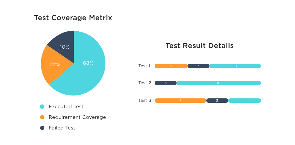
Why Test Coverage Is Important In Software Testing

Program Evaluation And Review Technique Wikiwand

Discover Top Startups Advancing Renewable Energy Startus Insights
Code Insights Team
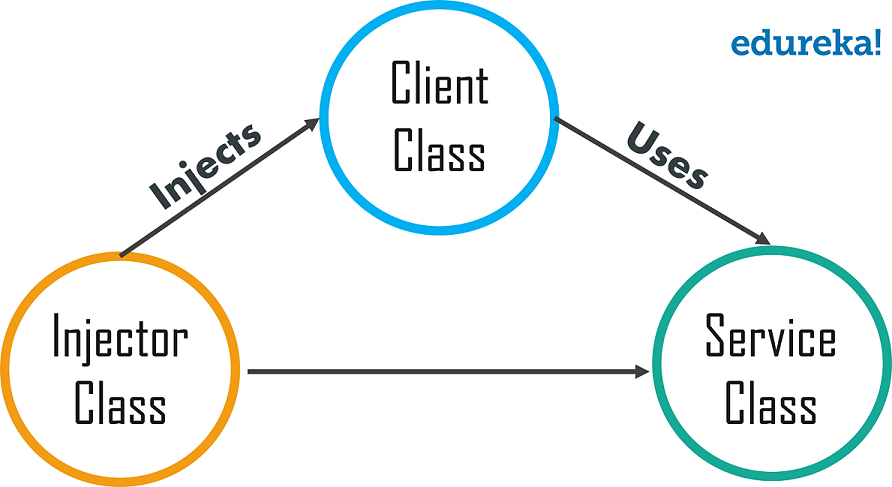
What Is Dependency Injection Dependecy Injection In Spring Edureka

Proxmox Ceph Full Mesh Hci Cluster W Dynamic Routing Packet Pushers
How To Show Dependencies In A Project Plan Quora

Top 10 React Graph Chart Libraries With Demo
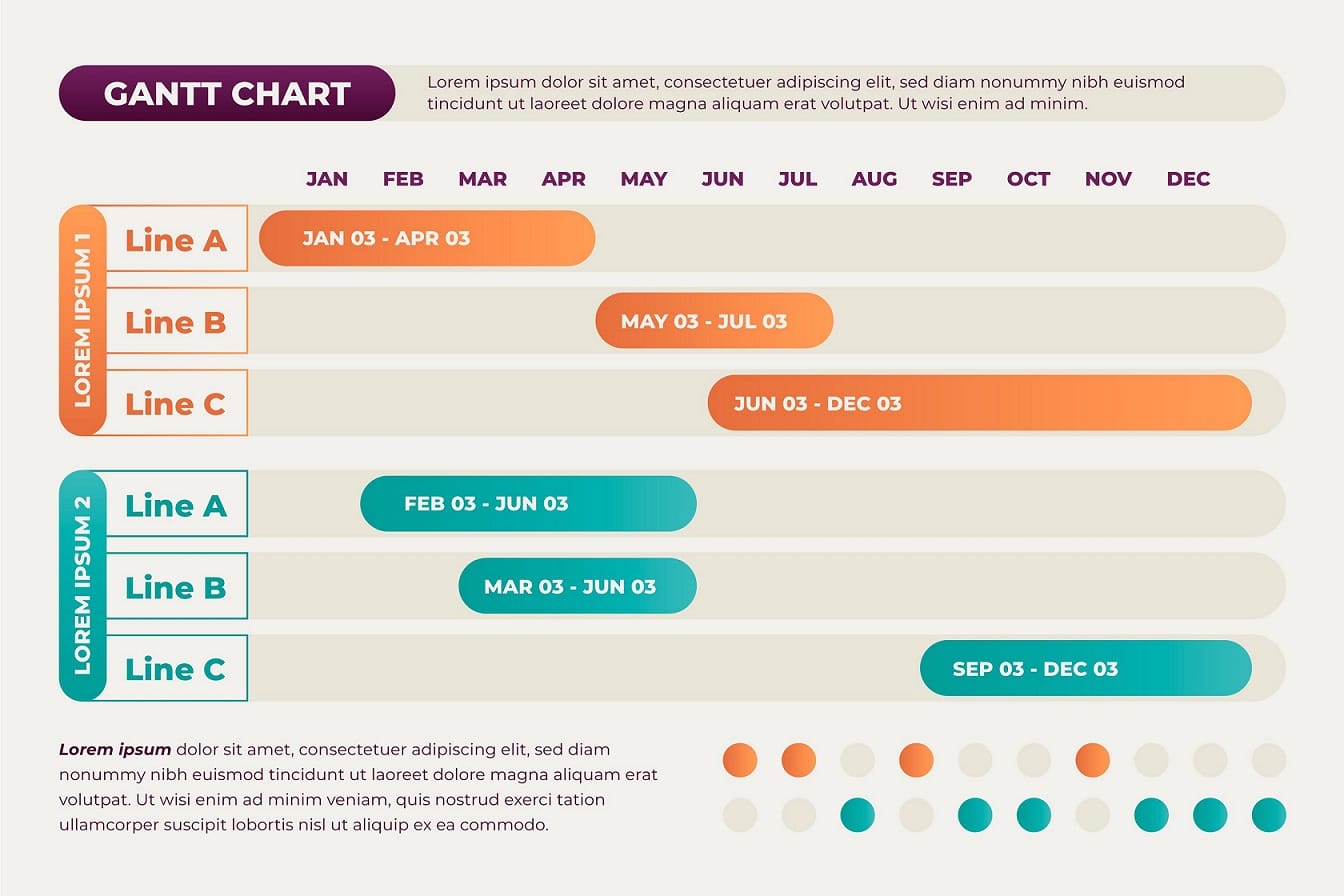
10 Best Free Google Slides Gantt Charts For Project Management

How Hystrix Works 官方 一天不进步 就是退步 博客园
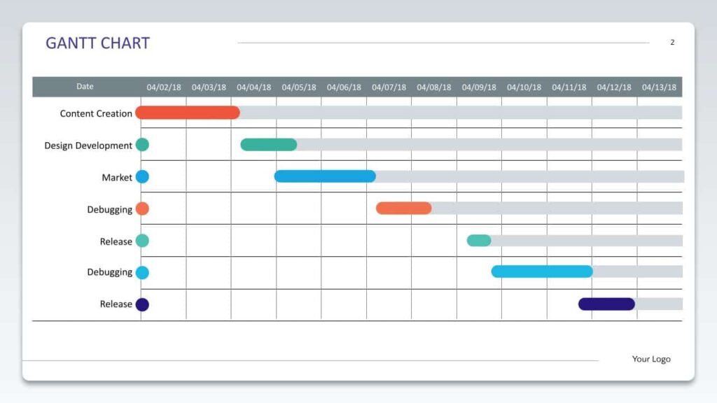
10 Best Free Google Slides Gantt Charts For Project Management
What Is The Difference Between Dependency And Association In A Uml Class Diagram Quora

Tree View Hierarchical Breakdown Of Dependencies Subitems Bit Like Org Chart Feature Feedback Monday Community

Dependency Analyzer Brittany Weigandt
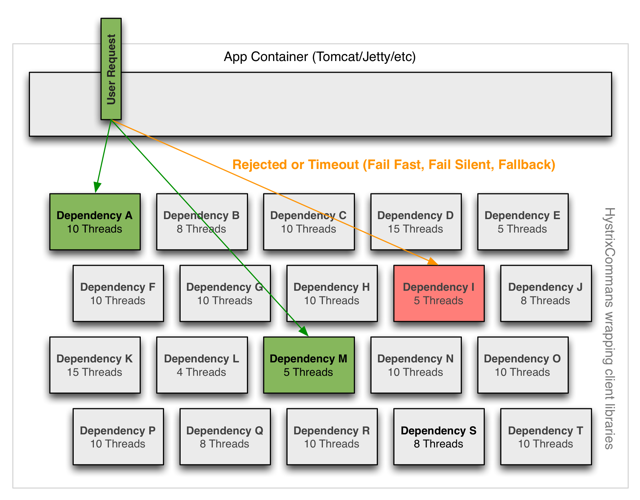
How Hystrix Works 官方 一天不进步 就是退步 博客园